CNC Engraving and Milling for Aluminum Mold Manufacturing: Principles and Precision Control
KAIBO CNC
2026-03-30
Tutorial Guide
This guide provides a technical, application-oriented overview of CNC engraving and milling machines used in aluminum mold manufacturing. It explains core working principles (motion axes, spindle dynamics, servo control, and interpolation), and summarizes the key machine parameters that most directly affect quality—spindle speed range, rigidity, thermal stability, and positioning accuracy. It then details practical methods for controlling machining precision, including datum strategy, tool length/radius compensation, backlash and pitch error compensation, probing and in-process measurement, and temperature management. Tooling selection is discussed with aluminum-specific considerations such as chip evacuation, coating choices, and edge geometry to reduce built-up edge and improve surface finish. The article also outlines essential CNC system functions—high-speed machining (HSM) algorithms, look-ahead, jerk control, and adaptive feed control—linking them to measurable outcomes like reduced contour error and improved repeatability. Finally, typical workflow optimization patterns and common bottlenecks (chatter, deformation, burrs, and polishing allowance control) are addressed through case-based practices to help manufacturers strengthen throughput and mold quality, building a sustainable competitive advantage for teams adopting Kayabo CNC best practices.
CNC Engraving & Milling in Aluminum Formwork Manufacturing: Working Principles and Precision Control That Actually Hold on the Shop Floor
In aluminum formwork production, CNC engraving & milling machines sit at a critical intersection: surface finish, dimensional accuracy, and repeatable throughput. For decision-makers and process engineers, the core question is no longer “Can we machine it?” but “Can we keep accuracy stable across batches, shifts, and tool life—without sacrificing cycle time?” This guide explains how CNC engraving & milling works for aluminum molds, how accuracy is controlled in real operations, and what to watch in tooling and CNC system functions—framed with practical checkpoints that teams can adopt quickly.
1) Working Principle: What the CNC Engraving & Milling Machine Is Really Doing
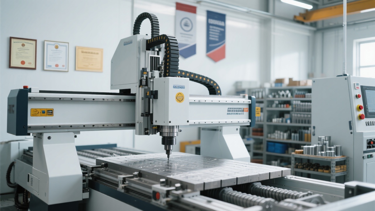
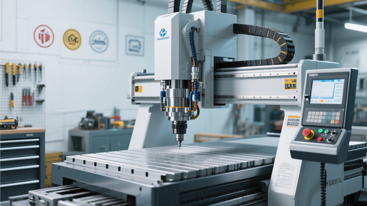
A CNC engraving & milling machine executes a closed-loop motion-and-cutting process based on G-code (or CAM-generated toolpaths). In aluminum formwork/mold components, typical operations include rough milling, semi-finishing, fine contouring, engraving/marking, and pocket/slot machining. The machine’s value is not only “automation,” but its ability to coordinate spindle speed, feed rate, toolpath curvature, and axis dynamics to keep cutting stable.
Core motion chain (practical view)
CAD model → CAM toolpath → Post-processor → CNC controller → Servo drive → Ball screw/linear motor → Axis position feedback → Tool meets aluminum.
In many aluminum mold/formwork applications, most “mystery” defects—chatter marks, corner overcut, inconsistent depth, burr formation—are not random. They come from predictable interactions: machine stiffness + tool geometry + aluminum’s tendency to build up edge (BUE) + controller dynamics.
2) Precision Control: How Shops Keep Tolerances Stable (Not Just on Day 1)
In aluminum formwork manufacturing, common dimensional targets for functional features (interfaces, sealing faces, locating slots) often sit around ±0.05 mm to ±0.10 mm, while critical mating surfaces can require ±0.02 mm depending on assembly method and downstream fit-up. Real precision control is a system: machine condition, thermal behavior, fixturing, tooling, program strategy, and inspection feedback.
Accuracy stack-up checklist (fast to implement)
Warm-up & thermal stability: allow spindle/axes to stabilize (often 15–30 minutes in production routines).
Backlash & axis calibration: verify with ballbar/laser checks periodically; compensate in controller where appropriate.
Workholding rigidity: minimize unsupported span; avoid “soft clamp” that changes under cutting load.
Tool length control: presetter measurement + tool wear offsets; track tool life by cut time or part count.
A practical way to communicate capability—internally and to customers—is to align with recognized measurement logic. Many manufacturers reference ISO 230 series for machine tool test methods, and adopt GD&T practices aligned with ASME Y14.5 for feature control and inspection communication. Even if a shop doesn’t run full certification cycles weekly, adopting a “standard-based language” improves cross-team interpretation and reduces rework.
Look-ahead + jerk control + smoothing + proper cornering strategy in CAM
3) Tool Selection for Aluminum Mold/Formwork: Geometry Beats “More RPM”
Aluminum is forgiving in cutting force but unforgiving in chip control and edge buildup. That’s why selecting tools for aluminum formwork machining should prioritize: sharp cutting edges, polished flutes, and proper chip evacuation. For many profiles, a 2–3 flute carbide end mill is used to balance chip space and tool rigidity.
Common winning combinations
2-flute polished carbide: strong chip evacuation for slots/pockets.
3-flute aluminum-specific: higher feed potential with stable finish.
Ball nose end mill: finishing 3D contours and radii transitions.
Engraving tool (V-bit / small-end): marking, fine details, shallow text.
Coolant & chip strategy (often underestimated)
For aluminum, consistent chip evacuation is frequently the difference between “stable accuracy” and “random rework.” Flood coolant, air blast, or MQL can work—what matters is keeping chips away from the cutting edge and preventing BUE. In many shops, burr rate drops notably once chip recutting is eliminated.
A practical rule used by experienced operators: if surface finish suddenly worsens while the program is unchanged, check for chip packing and edge buildup before chasing offsets. That single habit can save hours of trial-and-error.
4) CNC System Functions That Matter in Aluminum Mold Work
Buyers often compare machines by spindle power or travel, but in mold/formwork engraving & milling, the CNC control features can be equally decisive—especially for fine edges and 3D transitions. The functions below are frequently linked to measurable improvements in consistency:
High-impact controller capabilities
Look-ahead & path smoothing: reduces corner marks and feed fluctuations on complex toolpaths.
Jerk/acceleration control: improves contour accuracy, especially on small radii and engraving details.
Tool wear and length compensation: stabilizes size over long runs; supports scheduled corrections.
Probing/measurement macros: faster datum setting, reduced setup variation between operators.
5) A Practical Process Optimization Example (Typical Aluminum Formwork Part)
A common optimization pattern in aluminum formwork manufacturing is moving from “one-pass finishing attempts” to a structured flow that controls deformation, heat, and tool wear. One typical route used by process teams:
Optimized route (shop-friendly)
Datum strategy fixed (A/B/C) and probing routine applied.
Roughing with consistent stock allowance (0.2–0.5 mm).
Semi-finish for geometry stabilization (remove bulk stress).
Finish with lighter radial engagement and stable feed.
Deburr strategy planned (not improvised).
First-article inspection + sampling plan for batch.
What changes in outcomes
When roughing stock becomes consistent and finishing is protected from vibration, many shops report noticeably fewer corner defects and less “offset chasing.” In real production, even a 10–20% reduction in rework time can translate into more predictable delivery and better capacity planning.
From a competitiveness standpoint, precision control is not a “nice-to-have.” When aluminum formwork projects scale, the winner is often the supplier that can keep quality consistent across production lines—because consistency reduces downstream assembly friction, on-site adjustment, and project delays. This is also where 凯博数控 teams often focus their internal process discipline: turning machine capability into repeatable manufacturing performance.
Technical Q&A (Join the Discussion)
Q1: Why does the size “creep” after a few hours even when the program stays the same?
Most commonly: thermal drift (spindle/axis), tool wear/BUE, or chips trapped at datums. A quick isolation test is to re-probe datums and measure a control feature; if the datum shifts, suspect setup/thermal. If datum is stable but feature grows/shrinks, suspect tool edge condition and wear compensation strategy.
Q2: For aluminum engraving details, is higher RPM always better?
Not always. Fine engraving depends on stable chip formation and minimal vibration. Excess RPM with weak chip evacuation can increase BUE and edge tearing. Many teams get better results by reducing tool overhang, using a sharper geometry, and enabling controller smoothing—then tuning feed/RPM together.
Q3: What’s the one process setting you would standardize first across shifts?
Datum-setting and verification. A consistent probing routine (or a strict first-article method if probing isn’t available) typically reduces operator variation faster than any other single change.
What tolerance range is hardest for your aluminum formwork parts right now—flatness, slot width, hole position, or surface finish? Share the failure pattern and your current tooling/coolant approach.


.png?x-oss-process=image/resize,h_100,m_lfit/format,webp)
.png?x-oss-process=image/resize,h_100,m_lfit/format,webp)
.png?x-oss-process=image/resize,h_100,m_lfit/format,webp)